
- All
- Product Name
- Product Keyword
- Product Model
- Product Summary
- Product Description
- Multi Field Search
Views: 0 Author: Site Editor Publish Time: 2026-09-08 Origin: Site
Aggregate production profitability relies heavily on crushing efficiency. This efficiency degrades predictably as internal components wear down over time. Unplanned downtime disrupts plant schedules and creates massive operational bottlenecks. Reduced throughput forces operators to run longer shifts to meet production targets. Out-of-spec product gradation stems directly from degraded mantles and concaves. Coarse material overloads secondary crushers and screening circuits, causing a ripple effect of inefficiency. These compounding issues lead to severe operational cost overruns. Operators need a technical breakdown of cone crusher wear parts to maintain peak performance. Material selection frameworks must match specific geological profiles to maximize lifespan. Evidence-based replacement protocols prevent catastrophic mechanical failures. Implementing these strategies minimizes operational risk. It optimizes overall plant performance and maximizes aggregate yield.
Mantle and concave synchronization dictates crushing chamber efficiency; uneven wear directly impacts the closed side setting (CSS) and final product gradation.
Selecting the correct manganese steel alloy (e.g., 14%, 18%, 22%) depends strictly on the abrasiveness and crushability of the feed material, not just upfront cost.
Proactive daily calibration and scheduled wear inspections prevent catastrophic damage to underlying components like main shafts and eccentric bushings.
Evaluating replacement cone crusher parts requires analyzing wear life, maintenance intervals, and throughput, rather than unit price alone.
The mantle acts as the primary moving crushing face. It sits securely on the crusher head center. The main shaft and eccentric assembly force the head to gyrate in a circular motion. This gyration breaks rock against the stationary outer wall. As rock passes through the crushing cycle, the mantle endures massive impact. It also faces continuous abrasion from sliding rock under extreme pressure. Mantle degradation alters the closed side setting (CSS). A worn mantle increases the CSS unexpectedly. This drift leads to coarser product gradation. Operators must adjust the crusher constantly to compensate by threading the bowl downward. Eventually, the mantle profile changes completely. The crushing zone shifts higher or lower in the chamber. This shift reduces efficiency and increases power consumption.
The core of the mantle must remain ductile while the surface hardens. This duality prevents the liner from shattering under heavy loads. The geometry of the mantle determines the nip angle. The nip angle is the angle between the mantle and the concave. If the mantle wears unevenly, the nip angle increases. When the angle exceeds the friction limit, rock slips upward instead of crushing. This phenomenon causes the feed to boil, dropping production rates to near zero. You will see rock bouncing at the top of the chamber instead of pulling down into the crushing zone.
The concave provides stationary resistance. It interacts directly with the mantle to form the crushing chamber. As feed material enters, the concave holds the rock. The gyrating mantle applies compressive force to shatter the material. Concave wear alters the chamber geometry over time. The lower section usually wears faster due to higher crushing forces and a higher concentration of fine material. This uneven wear reduces reduction ratios. It decreases overall throughput and increases recirculating loads. The concave is secured to the upper frame or bowl. It must remain absolutely stationary during operation. Any movement causes severe damage to the bowl seating surface.
Different concave profiles exist for different feed sizes. Coarse, medium, and fine profiles dictate the maximum feed size the crusher can accept. Installing a fine concave for a coarse feed creates immediate blockages. The rock bridges across the top of the chamber. Conversely, a coarse concave with fine feed causes localized wear at the bottom. The upper section of the concave remains untouched while the bottom wears out prematurely. Matching the cavity profile to the actual feed gradation is a fundamental requirement for efficient crushing.
Several components secure the primary wear liners. Torch rings lock the mantle onto the head. Locking nuts provide massive clamping force. Backing compounds fill the microscopic voids behind the liners. They keep the mantle and concave firmly in place. Loose liners cause severe galling damage to the crusher head or bowl. Wear part integrity directly protects internal components. Eccentric bushings, thrust bearings, and main shafts rely on intact liners. If a liner cracks, the shockwave transfers directly into the bronze bearings, often destroying them instantly.
Dust sealing systems prevent rock dust from entering the lubrication oil. The seal ring and blower systems maintain positive pressure inside the machine. Lubrication systems mitigate friction inside the machine. They protect internal parts when massive crushing forces transfer through the mantle. Clean, cool oil absorbs the heat generated by the crushing action. If the liners wear too thin, excessive heat transfers into the head. This heat breaks down the oil viscosity, leading to bearing failure and massive repair bills.
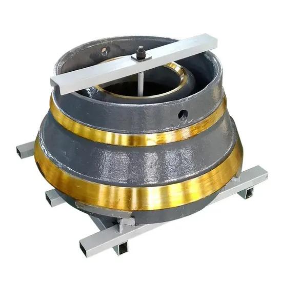
Austenitic manganese steel work-hardens under impact. The outer layer hardens significantly during operation. The inner core remains ductile and absorbs shock. This unique property makes it ideal for crushing applications. Without impact, manganese steel remains relatively soft. It will wear out quickly in purely abrasive environments like sand or gravel with no large rocks. The transformation from austenite to martensite on the surface provides the wear resistance needed for hard rock.
Foundries pour different grades of manganese to suit specific geological conditions. Selecting the wrong grade guarantees poor wear life. You must match the metallurgy to the rock's abrasion index and crushability.
| Material Grade | Impact Resistance | Abrasion Resistance | Best Application |
|---|---|---|---|
| Mn14 (14% Manganese) | High | Low | Large, hard rock with high impact forces (Primary/Secondary) |
| Mn18 (18% Manganese) | Medium | Medium | General aggregate and limestone crushing (Standard choice) |
| Mn22 (22% Manganese) | Low | High | Highly abrasive, smaller feed (Tertiary/Quaternary) |
| TiC Inserts | Medium | Very High | Quartzite, granite, and extreme abrasion environments |
| Martensitic Steel | Very Low | High | Slag or highly abrasive fine crushing with zero tramp iron |
Upgrading to TiC inserts makes sense for highly abrasive applications. Quartzite and granite wear standard manganese extremely quickly. Foundries cast Titanium Carbide rods directly into the manganese matrix. These inserts dramatically extend wear life. The manganese work-hardens while the TiC rods resist severe abrasion. Operators must conduct a strict operational analysis before upgrading. The premium cost of TiC inserts is justified through extended maintenance intervals. Fewer liner changeouts mean significantly less downtime and higher annual production.
Martensitic steels offer another alternative for specific applications. They provide high hardness throughout the entire thickness of the liner. However, they lack the impact resistance of austenitic manganese. Use martensitic liners only in low-impact, high-abrasion environments. If tramp iron enters a crusher with martensitic liners, the liners will shatter. Manganese, by contrast, will yield and deform, often surviving the tramp event without destroying the crusher.
Operators must recognize the difference between normal wear and premature failure. Normal wear occurs evenly around the circumference of the liner. The liner maintains its general profile until it reaches the minimum thickness. Localized wear indicates severe operational issues. Bell-mouthing occurs when the bottom of the chamber wears excessively. This happens when the crusher operates with a feed that is too fine. Cupping happens when a deep groove forms in the middle of the liner. This indicates the feed is too coarse or choke feeding is not maintained.
Root causes of premature failure include improper feed distribution. Segregation in the feed cavity forces the crusher to work harder on one side. Large rocks hit one side while fines drop down the other. This uneven load causes the head to tilt, damaging the eccentric bushing. Tramp iron events cause catastrophic localized damage. Uncrushable metal forces the liners to yield and deform. Incorrect chamber profile selection accelerates wear in specific zones. Using a coarse cavity for fine feed guarantees poor liner life.
| Wear Pattern | Visual Indicator | Root Cause | Corrective Action |
|---|---|---|---|
| Cupping | Deep groove in the middle of the mantle | Trickle feeding or feed is too coarse | Implement choke feeding; reduce top size of feed |
| Bell-Mouthing | Excessive wear at the bottom discharge zone | Feed contains too many fines | Screen out fines before the crusher; change to a fine cavity |
| One-Sided Wear | Liner is thin on one side, thick on the other | Feed segregation; material dropping off-center | Install a rock box or feed distributor above the crusher |
| Cracking | Visible fractures in the manganese | Tramp iron event or running liners too thin | Install metal detectors; adhere to thickness replacement limits |
Establish strict daily visual checks. Inspect the crushing wall and mantle for cracks. Look for deep gouges and structural damage. Catching these issues early avoids unexpected mechanical breakdowns. Use a high-powered flashlight to inspect the chamber while the crusher is locked out. Look for missing chunks of manganese. Track secondary production metrics as leading indicators of wear. An increased amperage draw signals that the crusher is struggling. The motor works harder to push rock through a deformed chamber.
A capacity drop indicates that the nip angle has changed. The rock slips instead of crushing. Recirculating load spikes also indicate worn liners. The crusher fails to reduce the rock on the first pass, sending it back through the screen. Monitor the hydraulic pressure in the tramp release system. Frequent pressure spikes indicate the crusher is packing. Packing occurs when fines cannot exit the chamber fast enough due to a worn lower profile.
Liners have specific thickness thresholds. The standard criteria for discarding worn parts vary by manufacturer. Most recommend replacement when the liner reaches 3/8 to 1/2 inch thickness at the bottom. Running liners too thin introduces massive operational risk. Thin liners can crack under crushing pressure. A cracked liner shifts and causes permanent damage to the head center or bowl. This leads to catastrophic breakdown and massive repair bills. Never push liners past their safe limits to save a few days of production.
During tear-down, assess the underlying steel structures. Inspect the head and bowl seating surfaces closely. Look for galling, pitting, or rust buildup. Determine if rebuilding or reconditioning is necessary before installing new liners. If the seating surface is compromised, the new liner will not sit flat. It will flex during operation, cracking the backing compound. Use a straight edge to check the bowl for out-of-roundness. Machining the bowl may be required if distortion is found.
Lock out and tag out the crusher main drive and lubrication systems to ensure absolute safety.
Remove the bowl assembly and clear any remaining rock from the crushing chamber.
Heat the torch ring carefully to cut it loose. Never cut directly into the crusher head with the torch, as this creates stress risers in the steel.
Lift the worn mantle using specialized lifting lugs and an overhead crane.
Clean the head and bowl thoroughly with wire brushes and grinders. Remove all old backing compound, grease, and rust.
Seat the new liners and prepare the high-quality backing compound. Mix the two-part epoxy according to strict temperature guidelines. Cold epoxy will not flow, leaving dangerous voids.
Pour the epoxy carefully to ensure full coverage behind the liner. Build clay dams to prevent leaks during the pour. Eliminate air pockets by pouring from one side only.
Observe proper seating and curing times. Do not rush the cure by applying external heat unless specified by the manufacturer.
Follow initial break-in procedures. Run the crusher empty for a short period. Then, trickle feed it with soft material to ensure the new manganese liners work-harden correctly before taking full load.
OEM parts guarantee fitment and warranty compliance. They offer predictable baseline performance. You know exactly what you are getting with every order. However, they come with a higher initial purchase price. Aftermarket parts provide potential for custom metallurgical upgrades. Independent foundries can alter the chamber profile to suit your specific rock. They offer significant cost-efficiency for high-volume operations. However, aftermarket sourcing requires strict vetting for quality control. Poor quality aftermarket parts will destroy a crusher from the inside out.
Advanced aftermarket suppliers use 3D laser scanning. They scan your worn liners to understand your specific wear patterns. Engineers then design a custom profile that wears more evenly. This reverse engineering maximizes the utilization of the manganese. Instead of throwing away a liner that is 60% intact, custom profiles ensure you use 80% of the metal before replacement. This drastically improves the efficiency of the crushing circuit.
Evaluate foundries based on strict technical criteria. Look for ISO certifications and documented quality management systems. Demand metallurgical transparency. Ask for material test reports (MTRs) for every single pour. Ensure the supplier provides dimensional accuracy guarantees. Poorly cast liners will not seat correctly. This leads to backing compound failure and internal damage. Check their heat treatment processes. Proper water quenching is essential for manganese steel.
If the cooling rate is too slow, carbide precipitation occurs at the grain boundaries. This makes the steel extremely brittle. The liner will shatter upon impact with hard rock. Partner with suppliers who understand your specific crushing application. Ask about their non-destructive testing (NDT) capabilities. Ultrasonic testing and magnetic particle inspection ensure there are no internal voids or surface cracks in the casting.
Calibrating cone crushers daily is non-negotiable. Adjust the closed side setting to compensate for liner wear. Perform a physical lead crush test or use automated hydraulic setting systems. This practice maintains consistent product gradation. It keeps the downstream screens operating efficiently without overloading the decks. Daily calibration also maximizes throughput. It ensures the crusher draws the correct amperage and utilizes the full power of the motor.
Failure to adjust the CSS leads to a cascading failure in the plant. The product becomes too coarse. The secondary crushers must work harder to reduce the oversized material. This accelerates wear on the secondary machines. The recirculating load increases, consuming conveyor belt capacity. A simple five-minute daily adjustment prevents hours of lost production and thousands of dollars in wasted energy.
Choke feeding maximizes uniform liner wear. It keeps the crushing chamber full at all times. This promotes rock-on-rock crushing, which reduces direct liner wear. The rock breaks against itself rather than grinding against the manganese. Trickle feeding causes localized wear at the bottom of the liners. The rock falls too far before being crushed, bypassing the upper crushing zones entirely. Maintaining a consistent, well-distributed feed cavity improves overall crushing efficiency.
Use a surge bin and a variable frequency drive (VFD) on the feed conveyor. This setup guarantees a steady flow of material. Ensure the feed drops directly into the center of the crusher. Use a rock box or a feed distributor to prevent segregation. If fines fall to one side and coarse rock falls to the other, the crusher will experience severe uneven wear. The eccentric bushing will suffer from uneven loading, leading to premature failure.
Differentiate between daily visual checks and scheduled major maintenance intervals. Replace worn parts before a major crusher breakdown occurs. Plan liner changes during scheduled plant shutdowns to minimize impact on production. Routine lubrication oil changes are critical. Inspect the tank for contamination regularly. Look for bronze or iron flakes in the oil filter. Worn liners generate excessive heat and vibration. This stress transfers directly to the eccentric bushings.
Clean oil protects internal components from this stress. Maintain proper oil temperature and flow rates. If the oil runs too hot, its viscosity drops. The oil film between the bronze bushing and the steel shaft breaks down. This results in metal-on-metal contact and catastrophic failure. Ensure the oil cooler is functioning correctly. Clean the radiator fins and check the cooling water flow. A healthy lubrication system is the only defense against the extreme forces generated by a worn crushing chamber.
Optimizing crushing chambers is a continuous, data-driven cycle. You must match metallurgy to the specific geological properties of your material. Execute precise daily calibration to maintain product gradation. Strictly time your replacements to avoid running liners too thin. Base procurement and replacement decisions on specific feed material data. Analyze historical wear profiles to improve future liner selection. Rely on supplier metallurgical consistency rather than default purchasing habits.
Audit your current crushing chamber profiles against your actual feed material size to ensure compatibility.
Establish a standardized daily inspection checklist for your operators, focusing on CSS measurement and visual damage.
Track amperage draw and recirculating loads daily to establish a reliable baseline for liner wear.
Consult with a qualified foundry for site-specific alloy recommendations based on your rock's abrasion index.
Implement a strict choke-feeding protocol using surge bins and VFDs to maximize uniform liner lifespan.
A: Wear life varies drastically based on feed material abrasiveness, crushability, and operating hours. In highly abrasive applications like quartzite, liners may last only a few weeks. In softer limestone, they can last several months. Tracking tons crushed rather than operating hours provides a more accurate measurement of liner lifespan.
A: The mantle is the moving inner crushing face attached to the crusher head. The concave, or bowl liner, is the stationary outer crushing wall secured to the upper frame. Rock is crushed between these two components as the mantle gyrates.
A: Uneven wear usually stems from poor feed distribution. If large rocks segregate to one side of the chamber, or if the crusher is not choke-fed, the liners will wear faster in specific areas. Correcting the feed arrangement resolves most uneven wear issues.
A: Choose Mn22 for highly abrasive, smaller feed materials where impact forces are lower. Mn22 offers superior abrasion resistance but lacks the high impact resistance of Mn18. If you crush large, hard rock, Mn22 may crack under the heavy impact.
A: Backing compound fills the voids between the liners and the crusher head or bowl. It provides solid backing, preventing the liners from shifting during operation. If the compound fails, the liners will move, causing severe damage to the underlying steel structures.
A: It is highly recommended to replace both components simultaneously. A new mantle paired with a worn concave alters the crushing chamber profile. This mismatch reduces crushing efficiency, creates poor product gradation, and accelerates wear on the new component.
A: The lubrication system cools and protects internal components like eccentric bushings and thrust bearings. Worn liners transfer intense vibration and heat into the crusher frame. Clean, cool oil absorbs this heat and prevents catastrophic metal-on-metal friction inside the machine.


